RiPPR
winter of 2010
Overview
In this article, we're going to learn how to build a preceise and extensible 2/2.5-dimensional laser cutter/engraver, made mainly from computer parts. The cost of the components shouldn't exceed 100$ in total. This laser engraver is capable of cutting black plastic details (CD boxes, tape, etc...) on the area of 4cm². You can also use it with some black tape to etch small and amazingly precise PCBs at home.
Components:
- Laser protection goggles: ~10$; (Look at the wavelenghts! You should be dealing with 650nm)
- An old 3.5" black HDD: free
- A few (9 to 12) M3 copper stands: free or 3$
- Two identical DVD-RW drives 20x+: ~18$/each (They must be the same models, it's crucial for the preciseness)
- An old CCTV camera's casing with a lens, or a laser collimator from eBay: free/5$
- A tube of thermal grease: 1$
- An arduino 16/32 [link]: 20$ (32 is better, it can be flashed with more features)
- Two EasyDriver Stepper motor drives [link]: 15$/each
- One ATX power supply or some 12-24VDC, 1A+ adapter/phone charger.
- One Laser Diode driver from eBay: 3$ _________________________________________ Total: around 95$, in case you don't have anything laying around ready to be used in your project.
About the laser driver: Remember, that you need to buy the one with the output current range of 400-450ma (maximum, 500), featuring TTL (Transistor-Transistor Logic), which is very important. I got mine from ebay for 3$ and that lot was called "constant current laser diode driver 80-500mA w/TTL" TTL means that it has 3 leads on input: GND (-), +V (Vcc) and Enable. You should apply some voltage to the third pin, to make the driver turn the laser on. We need it to be able to do that, no way you're going to cut more than one shape without TTL in your driver.
Before we start, I'm going to give you a list of tech terms you probably already know, but I just don't want you to get lost in science as you're reading, so here we go:
PCB - Printed Circuit Board ESD - ElectroStatic Discharge TTL - Transistor-Transistor Logic LD - Laser Dioie LED - Light Emitting Diode CNC - Computer Numerical Control CAD - Computer-Aided Design CAM - Computer-Aided Manufacturing G-Code - A numerical controlling language LASER - Light Amplification by the Stimulated Emission of Radiation.
Lasers __________________________*
This article has only some basic information about the lasers, enough to give for you to understand all dangers of dealing with them. First of all, remember this: never, but NEVER look at it, even when it "should be off", even through the goggles - NEVER! You WILL go blind, and it's for real this time. If you always get burns when cooking, or don't know how to cross the street, then better go play with some kind of another toy, seriously, I do not want to feel guilty for ruining anybody's life. You can see the powerful laser only twice in your life - every time with each of your eyes.
For this project, we're going to use some powerful semi-conductor diode lasers, just like the ones you can salvage from 16x+ optical DVD burners, or the ones that could be bought on eBay. Laser diodes typically use the same principle, as an LED: it consists of a crystal, has 3 leads (usually +, - and unused/infrared). The only difference is that they're much more sensitive to ESD than any other type of diode. Also, 90% of laser diodes will die if you attach them to the power supply, using wrong polarity. And one more thing: you never attach them straight to your battery, you should ALWAYS use the driver. Even in cases of "I'm just checking".
Tip: There's a little trick when dealing with ESD-sensitive components at home. If you do not have any anti-ESD bracers, carpets or a special soldering iron, then do this: each time, before touching anything, that you think you might damage, you touch with your bare finger something, that gives you a spark every time you touch it (that will get the discharge off you for some time). Don't touch your cat, you need some kind of a metal thing, such as your computer's case, or a metal part of some table. It's crucial to avoid any ESD damage, since it's a big frustration to ruin it like that, especially if it's something that you've purchased online and waited to arrive for days/weeks.
So, lasers. The ones you can salvage from your dvd-burner is usually a ~420mW laser diode, in case you've taken the fastest DVD-burner (burning DVDs at the speed of 24x). You should never consider playing around with anything below DVD, since burning CD drives carry only IR (Infra-Red) diode of approximately ~80mW of power. BluRays are more powerful, but they're very fragile. There're some 1Watt (1000mW) IR laser diodes available on eBay, but you should really know what you're doing when dealing with them, since they have a different pinout, they need a different kind of driver, you can never see if it's on or off (since our eyes cannot see in that spectrum). Besides, you need a special lens for the IR lasers: plastic, or made from a special glass, since typical glass lenses block infra-red. You can change your 'weapon' later, you just need to make your CNC work, so don't rush "out there", yet.
Here's the reference for the light wavelenghts:

Human eye cannot see in IR and Ultra-Violet spectres, so you should be aware of that in the first place. It's not just words, you can really lose your sight just like that, meters away from the source.
The one you're going to salvage from your DVD burner is 650nm, and it's definately red. You should never turn it on without wearing some protection goggles. I mean it.
To give you a little example, just for you to know: about a year ago, when I began dealing with diode lasers, I had to check if an old diode from a 20x DVD burner was still alive. I took a +3.7V battery and connected it to the leads, without any lens attached, wearing no protection gear, just holding it in my two hands, about 20cm away from my face. That diode turned out to be working, lid up and flashed for like 1 second, before I turned it off. The light has reflected from my hand and went straight into my right eye. I felt that I had some burn for a few good days after that, I couldn't see it, but I felt a soft 'darkness' in my right eye for about a week. Now, just imagine what happens if it's focused and you're looking right at it, while it's powered from a 400mA driver...
That's right.
Salvaging needed parts
First of all, we need a platform. I've chosen a 3.5" HDD, just because it's hard, has holes to screw copper stands in and it looks badass. Also, it has a flat surface to lay our materials on, and it's easy to assemble single controlling board in the future and place it on the bottom, to get a very solid device, without any wires coming from it. Also, make sure it's all black - you do not want to have any reflecting parts on the top, seriously.
Then you need to diassemble your Optical Drives for axiz. It's pretty easy, except for the part with the lens and the laser diode. Those diodes come inside a gray metal thing, called radiator. Constructions are all different, so you must be gentle while salvaging your diode from there. Don't go all shrek if it won't go, just think up something or read on the internet about some tricks. Do not use any hammers, you better spend another 30 minutes removing the glue, rather than buying a new drive for 20 bucks.
It's quite a big article already, so I'm just gonna give you a link to one awesome resource, which has a lot of information on how to salvage and mount your diode inside your collimator.
 Some of those diodes cannot be mounted after extraction, so you will have to keep it inside the radiator.
That's what happened to me, salvaging 24x drive.
I was very upset with that diode, until I found out that it was possible to use a CCTV camera casing, even with the stock lens. I had two lenses for CCTV, and only one of them worked well, since another one reflected the laser because of
some violet filter. The good thing is that glass lenses are always better than the plastic ones, and CCTV cameras have the right glass for it, remember how it can see ultraviolet and infrared on your phone, right? So it's not the best case, since it's an assembly of lenses, and that means that you're losing some power, but it's a glass, so it's still a good focusing tool for our cutter.
Another funny thing, is that the main part of those chinese collimators can be screwed inside the casing of CCTV camera.
I wonder if they make them both on the same factory.
It might not be the best case, but it's an easy way to mount a flat diode, which's impossible to put inside any regular round collimator. Flat diodes are lately being used inside 22x/24x DVD drives, so you can buy any 20x drive and be sure that you're getting a round (golden) one. Another way is to buy some round diode off eBay, and use 2 cheapest CD-drives just for sleds. The choice is after you.
I have to warn you about both HDD and the drives to have very powerful magnets. HDD has only one and VERY powerful, while the optical drives usually have 3 to 5 small, but still powerful magnets: 2 to 4 are used in the lens focusing assy, and one round is used in the upper part, in that little wheel which fixates the disc. Just make sure you're keeping them on distance from your laptop, iPod, external HDD or any other HDDs.
Also, never throw away any parts you get left over from your drives: there're a lot of good components soldered on, which you might need later.
Now you must have an empty HDD casing, two DVD-ROM sleds for X & Y and a laser diode salvaged.
Assembling
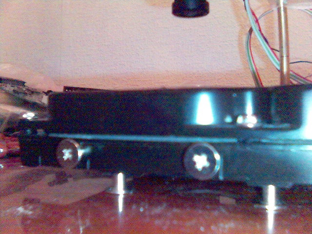
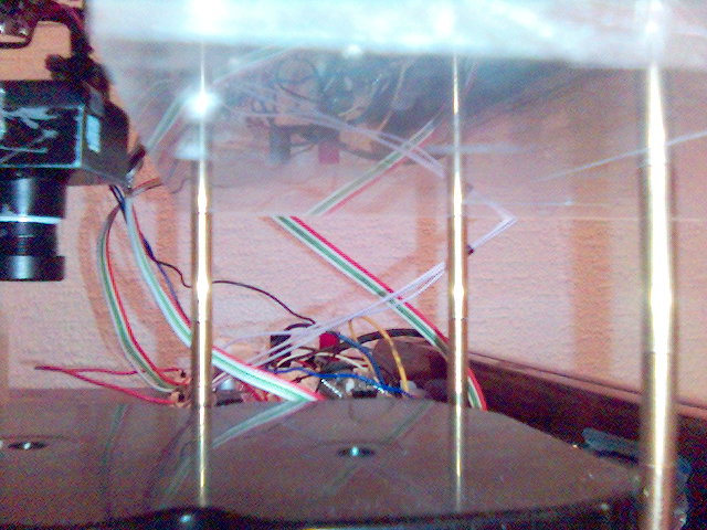 You take that empty HDD casing, screw in 3 copper stands (3 is the minimal amount, since 2 will not hold the mechanism horisontally, stable enough).
You screw in a few copper stands more, just to lift the upper part of our machine for about 5cm above the top level of our HDD.
Now you get a drill and make 3 good holes in some kind of a plexiglass or a metal plate. Just make sure that it's not curve and represents the same shape as on your HDD (you don't need any extra-tension on your copper stands). That piece should be made of metal/plastic, thick enough, to never really bend. It's a platform for our sled assembly, so it should keep the same angle, no matter what the position of our sleds currently is. You can take any material, even wood! Just make sure you can drill it at home, and it won't crack in half. The dimension must be capable of carrying one axis metal assembly you extracted from your optical drive.
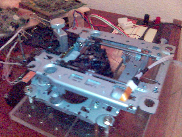
Now we have to assemble the X & Y mechanism. In two words, you just take one of them, flip over, screw on to the second one (contacting the same black plastic carrets, using the lens holes), and it's ready! If you're considering glueing it together permanently, then don't rush, make sure it's absolutely 90 degrees. Otherwise, you're going to get curve results every time you draw/cut anything. Also, keep in mind that this assembly won't be able to move even a glass of water. Those engines are small, so never overload the top (X) axis, othervise it won't draw straight. Avoid the usage of heavy parts, it's a small machine after all.
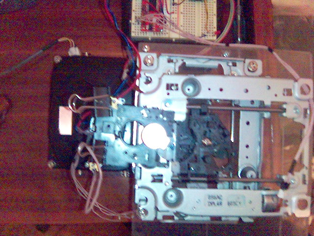 Now you screw that mechanism to the upper deck, drilling 4 more
holes in it for the screws.
Make sure that the moving part is still able to move! Otherwise, use some small copper stands to make it hover.
The best idea would be to cut out a huge rectangle underneath the moving part, but it's not that easy without having a bigger cnc. Ü
The last step is you attach your laser to the left side, pointing it down to the flat surface of your HDD.
Remember to SOLDER the diode STRAIGHT to your LD Driver. I've killed one diode by just having a bad contact out there. In two words, all drivers carry a smoothing capacitor, which should be discharged before connecting your diode to it. Otherwise the spike of current will burn you diode before you turn it on. So just make sure you isolate your driver good enough from any metal things around it, and never use any connectors leading to your precious diode, use only solid wires and a good solder!
This's the best kind of design I could find for this CNC, because it doesn't care about the weight of your material, you do not have to fixate anything and it's possible to add the third axis to it, even convert your machine to a 3D printer!
Hardware
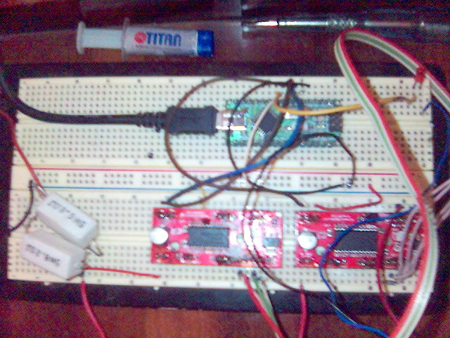
As for the hardware, now you will need 2 EasyDrivers, an Arduino and a Power Supply.
I assembled mine on a solderless breadboard, but you can just solder them together, it won't affect the performance.
Now it's pretty easy: you take your arduino, connect 2 wires to each of EasyStepper drives (STEP and DIR), then connect the grounds (GND) of all three boards together, then hook up the LD Driver to the Vout of your EasyDriver (that's +5v. Arduino has +5v too, but it won't be able to supply enough current to the driver), then attach the LD Driver's Enable wire to the arduino pin. nAfter that, you connect the power supply to the Vin of your EasyDrivers, then hook up your motors to A1, A2, B1, B2 pins on each drive, then turn the thing on! Don't forget about the polarity, double-check it before turning anything on.
Software
For the first version of my CNC, I had to write my own arduino sketch. It was a pain in the ass and it has never really worked straight. Then I discovered this amazing program. What it does, is that it turns your arduino into a motherboard, for any CNC. It has the full support of the software-level G-code. I wouldn't have succeeded in my project without that software. It runs on any Atmega-family chips, and therefore, on any arduino-like board. You have to compile it yourself, changing the settings, or just download the precompiled .hex file from the github.
To flash your arduino you should use this comand: avrdude -F -c avrisp -P /dev/ttyUSB0 -V -p m168 -b 19200 -D -U flash:w:grbl.hex (worked for my Arduino duemilanove Nano v4 [Atmega16]) Note: press the reboot button on your arduino just before flashing.
For flashing boards, based on Atmega32, you should set the flag -p to m328 accordingly. You could also use this command if you're building from a source: make flash Note: there're different trees on github for Atmega16 and Atmega32. You should know what kind of chip you got.
The full Grbl documentation is available here.
CAM
Today you can find any kind of CAD software tools. There're freeware and shareware ones available for windows and mac. For open-source community you can use emc2 under linux.
I wrote a small tool for converting SVG paths into G-Code, called svg2ngc.pl, you can get it here. Nothing fancy, but it works. The usage is:
./svg2ngc.pl sketch.svg
If you want to record the output to a file, execute it this way instead:
./svg2ngc.pl sketch.svg > sketch.ngc
My tools aren't professional and may not work as good as I'd want them to, but they're good for learning. It's not about software, after all, since Grbl uses the G-Code, you can write programs for it by hand, it's easier than working with vector graphics, believe me!
For feeding your G-code to your CNC, you may use a ruby script from the github
which comes with the grbl, or take my perl script.
All project files written by me can be found here.
Tip: there's a unix program called "screen", you can simply connect it to your arduino, using this command:
screen /dev/ttyUSB0 9600
There you can set any kind of configuration you want. Interesting thing is that those setting will be there even if you flash another version of Grbl above. This's really something.
Miscellaneous Info
My Grbl $ configuration:
'$' to dump current settings

Grbl 0.51
ok
$
$0 = 53.678 (steps/mm x)
$1 = 53.678 (steps/mm y)
$2 = 1.0 (steps/mm z)
$3 = 10 (microseconds step pulse)
$4 = 48.0 (mm/sec default feed rate)
$5 = 96.0 (mm/sec default seek rate)
$6 = 0.100 (mm/arc segment)
$7 = 0 (step port invert mask. binary = 0)

'$x=value' to set parameter or just '$' to dump
current settings
ok
Tip: You may tune your CNC, drawing single lines and boxes if you want to get the maximal precision possible. Then you just measure the result with a ruler and set the new $0=/$1= values in Grbl.
Tip: There're 2 G-Code commands to test the laser toggling function: M03 and M05. M03 will turn the laser on, and M05 off. I have an LED hooked up to my Enable wire, so that I always see if the laser is off or on. You can desolder an LED from one of those parts you've got left over your optical drive. Told you not to throw it away. Ü
My Grbl config.h pinout is:
//#define BAUD_RATE 115200
#define BAUD_RATE 9600

#define STEPPERS_ENABLE_DDR   DDRC
#define STEPPERS_ENABLE_PORT  PORTC
#define STEPPERS_ENABLE_BIT   2

#define STEPPING_DDR     DDRD
#define STEPPING_PORT    PORTD
#define X_STEP_BIT       2
#define Y_STEP_BIT       4
#define Z_STEP_BIT       0
#define X_DIRECTION_BIT  3
#define Y_DIRECTION_BIT  5
#define Z_DIRECTION_BIT  1

#define LIMIT_DDR    DDRC
#define LIMIT_PORT   PORTC
#define X_LIMIT_BIT  3
#define Y_LIMIT_BIT  4
#define Z_LIMIT_BIT  5

#define SPINDLE_ENABLE_DDR   DDRD
#define SPINDLE_ENABLE_PORT  PORTD
#define SPINDLE_ENABLE_BIT   6

#define SPINDLE_DIRECTION_DDR   DDRD
#define SPINDLE_DIRECTION_PORT  PORTD
#define SPINDLE_DIRECTION_BIT   7
I've set the EasyDriver current to about 20%, and it's quite enough. You may experiment with the amount of current yourself, but just touch the motors from time-to-time, to make sure you won't burn the coils. Don't be afraid about the temperature of the driver chips tho - they got an internal protection against ESD and overheating (they will just shutdown themselves if something goes wrong). As far as for the LD Driver, you should know what kind of diode you're driving. Mine will burn out at 460mA, so I never screw it to the full, I use it around 430mA. If you're concerned about the output power, then it should be around 400mW. I cannot make any real calculations since I don't know which voltage my driver supplies te the LD. Material has a bigger value here than the output power.
Z
About the third axis and focusing. It may sound stupid, but it's actually a very smart move to attach a third (Z) axis to a laser CNC. In a few words, it's just to always keep the laser focused on the surface. It works as a 'transparent spindle' in sorts. More info available here. Also, that way you might get a 3D printer and a laser engraver/cutter in one device. XYZ is always better than XY.
What I'm Working on Right Now
It's still a working prototype. I'm developing a single PCB, which would include all in-one: Atmega32, a USB chip and all 3 EasyDrivers. I'm also trying to develop a mechanism for the third axis to carry the laser, minimizing any possible vibrations. I'm attaching a small USB camera to save my eyes and control the CNCing process from a distance. Ventillation is another important thing I'm thinking about. That smoke from the plastic you burn is very bad for your health. I thought about the 'bubbler-like' filtering method, but it looks like a good old 10cm airconductor will do the magic.
